Introduction
Hardware Root of Trust
Exploring OpenTitan and Pavona
Overview
This material is provided by RISC-V Ottawa as a hands-on study of the hardware root of trust (HWRoT): a small, trusted core that everything else in a secure system depends on.
Rather than reading about it in the abstract, we take a real open-source root of trust implementation, boot it in a simulator on a laptop, and pull it apart subsystem by subsystem until the whole chain of trust is understood end to end.
The final goal is to get to the point where we can use a HWRoT in the same way a real product would. For this, we’ll focus on the discrete secure element use case, where a separate host processor communicates to the HWRoT over SPI.
The two open implementations we study are OpenTitan, the open silicon root of trust from lowRISC, and Pavona, the newer, certification-aligned design derived from it that adds a post-quantum crypto stack. Everything here runs in simulation using Verilator, so you need no special hardware, only a machine with enough memory to build it.
No prior hardware-security experience is assumed, though comfort with C, the command line, and the basics of public-key cryptography will help.
How the book is organized
The point of this book is not to rehash the already stellar documentation provided by OpenTitan and Pavona. Instead, it is to get you to look, understand, simulate, integrate, simulate again, break, and teach. It opens with the ideas, what a root of trust is, why open silicon matters, and which threats it is built against.
The chapters after that each take one subsystem of the chip (secure boot, secure storage and lifecycle, identity and keys, attestation, post-quantum crypto, provisioning and ownership) and follow it from the specification down through to the RTL and the firmware that drives it, ending in an exercise you perform yourself.
The final part is the most exciting, since this is where we stop treating the chip as a lab specimen and instead use it as a real component: a secure co-processor serving a host that has to trust its answers.
Don’t jump to the end though! Because every chapter ends in something you can simulate yourself and show off, e.g., a waveform, a boot log, a certificate chain that validates, or a run that correctly refuses to proceed.
As mentioned, the reference documentation from OpenTitan and Pavona is excellent and we link to it constantly rather than restating it; what this book adds is the narrative thread through it, a live simulation on your own machine, and a view of the internal state running in your own simulation environment.
What will you learn?
By the end you should be able to:
- Explain what a hardware root of trust is and how it is built from open silicon
- Build and run a real root-of-trust chip entirely in simulation
- Trace the secure boot chain from immutable ROM up to owner firmware
- Follow a device identity from an OTP root secret through key derivation to an attestation certificate that a remote service can verify
- Reason about secure storage, lifecycle states, and post-quantum cryptography
- Provision a blank simulated chip and hand ownership of it to someone else
- Utilize the chip from a host processor as a secure co-processor, and understand the attack surface between them and what defenses are provided
The goal is to gain fundamental and transferable knowledge on what it takes to have trust rooted in hardware.
What is a Root of Trust?
There is an old story about what holds up the world. Some ancient cultures pictured the Earth resting on the back of a giant turtle…which invited the obvious follow-up question: what holds up that turtle? Answer: another turtle. And under that one? Another turtle. It is turtles all the way down.
Every secure device you rely on, your phone, your car, the servers your bank runs on, is built the same way. It is layers, and each layer is forced to trust the layer underneath it. Your operating system trusts the bootloader that started it; the bootloader trusts the firmware before it; that firmware trusts the very first instruction the processor ever executes. Turtles, all the way down. Except a device cannot do this forever. At the very bottom there has to be one final turtle, and the entire stack is standing on it.
A hardware root of trust is that final turtle: a small, immutable piece of silicon that holds the device’s identity and its secret keys, decides what software is allowed to run at all, and that nothing else vouches for. Nothing else can, which is what makes it different in kind from every layer above it. It also sets a hard constraint. The final turtle has to be small enough to audit and simple enough to reason about, because a flaw in it cannot be patched by anything above it. Egret’s boot ROM is 32 KiB. The entire security argument of a device can rest on code that would be a rounding error inside an operating system kernel.
This chapter builds the mental model the rest of the book depends on: the five jobs a root of trust has to do, and how the blocks of a real chip map onto them.
The five jobs
The final turtle does five things. Everything else in this book is one of these jobs examined up close.
- Identity. Something no other device can claim (no matter how hard they try), descending from a secret the chip is born with and never reveals. An identity is something you can’t copy or overwrite.
- Secure boot. The process to ensure a system can refuse to run code that is not signed by a trusted authority, This is started at the very first instruction, before any mutable code gets a chance to lie about itself. A gap at the start of the chain leaves a gap in the entire chain of trust.
- Attestation. Proves to a remote party what hardware and software the device is actually running, in a form that the party can verify independently.
- Secure storage. Keep secrets and state confidential and tamper-evident against an attacker who physically holds the chip, opens the package, and reads the memories directly, which is a threat that the Pavona threat model calls out explicitly.
- Cryptography. Hashing, signing, key exchange, random number generation, and, more recently, post-quantum signatures, provided in hardware so they are fast, constant-time, and hard to observe. Protecting against side-channels here is crucial, since an algorithm that is mathematically correct but leaks its key through timing or power consumption is a broken algorithm.
These five are not separate features bolted together. Identity depends on secure storage to hold its root secret and on cryptography to derive keys from it; attestation signs its evidence with those keys; secure boot checks signatures with the same primitives. Egret wires that dependency directly into the hardware.
The jobs mapped onto Egret

Egret is a concrete instance of everything discussed above The datasheet’s top-level block diagram given above shows the Ibex RISC-V core, the memories, and the peripherals on one bus. Read against the five jobs, that diagram sorts into five groups.
| Job | Egret blocks that do it |
|---|---|
| Identity | Key manager (with DICE support), OTP memory (holds the root secret), KMAC (performs the key derivation) |
| Secure boot | ROM (verified on boot), the Ibex core’s ePMP (isolates each boot stage), asymmetric cypto and the boot ROM software (verify the next stage’s signature) |
| Attestation | Key manager (derives the identity keys that sign the evidence), asymmetric crypto (does the public-key signing) |
| Secure storage | OTP and flash (which has access control plus memory scrambling), the ROM and SRAM controllers (scrambling), and life cycle controller (gates what the chip will do at all) |
| Cryptography | AES, HMAC, KMAC, asymmetric crypto (RSA, ECC, and the lattice-based post-quantum algorithms), CSRNG with entropy source (randomness) |
Several blocks appear in more than one row, this overlap is on purpose. When later chapters zoom into one of these blocks, you can refer back to this table to see how it connects back to the whole.
The rest of the book is, in a sense, a slow walk through these table rows, one block at a time, first to understand what each one guarantees and then, in the final part, to integrate this within a larger system to find out what it does, and does not, do.
Why open silicon: OpenTitan and Pavona
In almost every device shipping today, the final turtle is a black box. The design is secret, the firmware is sealed, and you are asked to trust it because the vendor says so. That is a strange arrangement for the one component whose failure nothing else in the system can compensate for. A root of trust asks to be trusted absolutely, which is precisely why it should be open to inspection. When the RTL, the boot ROM, and the verification environment are all public, the security argument can be checked by anyone who cares to, and the design earns trust by being examined rather than by being hidden.
OpenTitan, from the lowRISC project, is where that
changed. It is the original open-source silicon root of trust, open all the way
down to the chip design itself, and it runs on RISC-V. It is also not a paper
design. As of March 2026, OpenTitan silicon fabricated by Nuvoton
ships in commercially available Chromebooks,
the project’s first production deployment. Its top_earlgrey
configuration is the most thoroughly documented, and its silicon_creator C
code is the reference implementation of secure boot.
Open here means more than a published block diagram. Both designs in this book
ship their Verilog, their silicon_creator C code, their register descriptions,
their design verification testbenches, and their threat model under Apache 2.0.
That is also what makes this book possible at all. You cannot single-step a
proprietary secure element, and you certainly cannot watch its key manager
change state. In simulation, on open RTL, you can watch any signal in the
design.
Pavona is the newer design, built in part from OpenTitan
and steered by a foundation hosted by GlobalPlatform with
certification readiness as an explicit goal. It keeps OpenTitan’s architecture
and much of its software, and adds the acc asymmetric cryptography
coprocessor: a separate processor with its own memories and its own big-number
ISA, running RSA and ECC today and carrying vectorized instructions for the
lattice-based ML-KEM and ML-DSA algorithms. Pavona is the reference we actually
build and run, and the configuration that we focus on is top_egret, the
discrete secure microcontroller we will boot, decompose, and break.
Note, the two projects and implementations play slightly different roles in this book.
Egret is what we run. Every command you type, every boot log you read, and
every block you break is Egret in Verilator. Earl Grey is what we read when
Egret’s own documentation is unclear or lacking, which it may be, because OpenTitan is older,
more thoroughly written up, and the so-called silicon_creator code it has is the canonical
secure-boot implementation. The two are close enough that most of what you learn
about one transfers to the other, and this book says so explicitly each time it
steps from one to another.
Threats and trust boundaries
“Secure” is not a property a chip can have on its own. Every security claim is relative to an attacker with particular capabilities, and to a boundary that separates who is in charge of what. Pavona documents both, and both are scoped to Egret (and Dragonfly), so they describe the exact chip we are about to boot:
- The lightweight threat model says who is attacking and with what.
- The logical security model says who is in charge at each stage of the chip’s life.
One tells you who is trying to tip the final turtle over, the other who is entitled to stand on it. Read them early. Nearly every later chapter is one row of one of these two documents examined in hardware.
Who is attacking
The threat model names three attacker profiles:
- Physical access, during manufacturing or out in the field.
- Malicious device owners, attacking a device they legitimately possess in order to develop an attack that works on every other device of the same type.
- Remote actors, who can still measure side channels at a distance.
These are each interesting on their own, but let’s consider the second one for a second. A root of trust has to keep secrets from the person holding it, which is obviously harder than keeping secrets from someone across a network…this will explain some of the design decisions we’ll encounter that might look paranoid, until you accept the threat model that’s been chosen.
The attack surface is correspondingly wide: the chip surface itself, open to inspection, reverse engineering, and physical manipulation; the operating environment, meaning temperature and power; peripheral interfaces and the APIs exposed at the device boundary; the test and debug interfaces; the clock, power, and reset lines. Pretty much everything! It of course even includes the documentation and design data, which is the whole “open silicon” thing. But, interestingly, publishing the design is actually covered by the threat model, not a violation of it! This is because none of the security is meant to rely on obscurity (i.e., the design being secret).
The methods split into three families:
- Logical. Software bugs reachable through an interface, compromise of secure boot, impersonation of the silicon creator or owner, misuse of test and debug functionality, insider compromise of provisioning.
- Non-volatile memory. Firmware downgrade, data rollback, command replay. These target time rather than secrets, forcing the device back into a state that was valid once.
- Physical. Passive side channel analysis, extracting a key by watching execution time, power draw, or electromagnetic emissions while the device runs perfectly normally, and active fault injection, pushing voltage, clock, temperature, EM, or a laser outside specification to make the device skip a check or corrupt a comparison. Any combination of these are in scopes too.
Due to all of this, it becomes apparent why a large fraction of Egret is not actually compute or cryptography at all. Instead, as we’ll learn, it is redundancy and integrity checking: dual-core lockstep, bus and register file integrity, shadowed registers, hardened counters and program counter, alerts that escalate, and more. None of this helps against bad cryptography. All of it exists because of the rather terrifying number of physical-attack methods.
Who is in charge
The logical security model draws the other boundary, and it is about entities rather than adversaries. A Pavona chip deals with up to three over its lifetime:
- Silicon Creator. Designs, manufactures, tests, and provisions the chip with its first identity, the Creator Identity, which is what proves the chip is genuine.
- Silicon Owner. Whoever currently owns the device. It validates the Creator Identity, provisions a second identity of its own that the creator does not know, and supplies the functional software stack.
- Application Provider. Supplies the applications running on top of that stack, and can derive further identities from the owner’s, isolated from each other by owner software.
Note that these roles are “logical”, meaning they can also collapse. One vertically integrated company that creates the silicon and provisions all of its software leaves a single identity rather than two (essentially the TPM model).
The boundary is drawn in software stages, and owning a stage means controlling the key that signs it. The Silicon Creator owns the ROM, immutable after manufacture, and the ROM_EXT, a modifiable extension that patches hardware issues, applies the security settings judged too risky to hard-wire into ROM, and performs creator identity provisioning. As those stages run they lock out the parts of the chip that later stages have no business touching, and they do not execute again until the next reset. Everything after that belongs to the owner. Because creator code is measured into the Creator Identity, and because it is open, a prospective owner can inspect exactly what it is inheriting before accepting a chip.
Taking all of the above sections together, we see how the threat model tells you what a given mechanism is defending against, defining attacker profiles demonstrates how intense things can get out in the real world, and the entity model tells you whose key forms the base of trust at each step along the boot chain. When we trace from the initial ROM all the way up to owner firmware, or watch a device carry two separate identities, or step through a lifecycle transition, we must keep this model and its boundaries in mind.
Booting a chip on your laptop
The entire Pavona Egret design and source is completely open. You can read, edit, and create a cycle-accurate model of the whole chip that can run directly on the laptop in front of you. So, let’s get hands-on!.
By the end of this part, you will have compiled the chip into a simulator, booted real software on it,
watched control pass from ROM to flash, printed Hello World! over a simulated
UART, and traced those characters back to the exact hardware registers used.
Everything runs in Verilator, which magically translates synthesizable Verilog into a C++ program. This allows you to exercise things one clock edge at a time. But be warned, this fidelity has some costs, for example, the first build may take on the order of ten minutes, and booting the thing (which, in real silicon would finish in milliseconds) takes about a minute. Not that bad though! And what this buys you is visibility no physical chip can offer. Ibex writes out every instruction executed, and any signal anywhere in the design can be dumped to a waveform, including signals that would not reach any pin on real silicon. Clairvoyant!
Note
Booting a chip and securing a chip are different achievements. What we are about to run is the test ROM, a development image whose own README calls out as testing-only, and it verifies no signatures whatsoever. The real secure boot ROM lives in
sw/device/silicon_creator/romand is subject to later parts. This part is just to show the chip coming up, that it runs our code, and how we can watch it happen.
The chapters for this part:
- Development environment sets up the toolchain (Bazel, fusesoc, Verilator, and the Python tooling).
- Building Egret in Verilator covers building the chip, from RTL through fusesoc to a compiled simulation binary, and the three memory images it boots from.
- Hello, World! boots real software, reads the log line by line, and turns on the instrumentation.
- Reading the memory map closes the part by mapping the chip so you can navigate and locate each block by address.
Every command here is one you run against your own Pavona checkout, and you walk away with a reproducible green boot you can get back to from a clean tree.
Development environment
Before you can build a chip you need the tools that turn its source into something runnable. Pavona’s toolchain is larger than a typical firmware project’s because it spans two worlds at once, hardware and software…and the same repository builds both. Understanding what each tool does makes the setup feel less like wizardry and more like a normal down-to-earth toolbox.
At the center is Bazel, invoked through a wrapper script
called bazelisk.sh that fetches the exact Bazel version the project expects.
Bazel is the single entry point for almost everything. It builds the RISC-V
software that runs on the chip, and it also drives the hardware build. When you
ask Bazel for a sim_verilator target, it runs
fusesoc to gather the RTL, invokes Verilator
to generate and compile the C++ model, builds the device software, and finally
launches
opentitantool
to load the memory images and stream the chip’s output back to your terminal.
You rarely call Verilator, fusesoc, or the opentitantool yourself; Bazel orchestrates
them, which is why nearly every command in this part starts with ./bazelisk.sh.
Note
Bazel is like
make…but on steroids. You name a target and it works out what to rebuild just likemake, except Bazel also goes and fetches its own tools (Verilator included), runs every step sandboxed so the result does not depend on what is lying around your machine, and caches test results and not just build outputs.
In the container we’re going to use, Verilator is built from source rather
than installed from a package, because distribution packages tend to lag badly
behind. Pavona pins the version in third_party/verilator/extensions.bzl (5.046
at the time of writing) and Bazel compiles it for you the first time you build a
simulation target. That compile is the bulk of the first ten-minute wait, and it
only happens once as long as Bazel’s cache survives, which is why the
container instructions below bind-mount a directory for it. Second, the Python tooling (topgen, regtool, dvsim, and the
scripts that generate register files and documentation) runs in a
project-specific virtual environment, installed from python-requirements.txt
with version/hash pinning, so its dependencies never collide with any system Python packages in the container.
There are two options to get your dev environment set up. Pavona’s getting started guide documents a native one running on a Ubuntu host. It works well if you already run a supported Ubuntu version. The container path below is the simpler option and works more broadly, thus it is what the rest of this book assumes.
Containerized build with Podman or Docker
Pavona provides a container definition at util/container/Dockerfile, built on
Ubuntu 22.04, that installs every system dependency the getting started guide
lists. Your locally checked out version of the Pavona repo stays on the
host and is bind-mounted in, so your edits and your git history live in one
place and outlive any container you recycle.
Bazel’s build cache does not, unless you mount a second directory for it. By
default Bazel caches under ~/.cache/bazel, and inside the container that
resolves to /home/dev/.cache/bazel, which is not part of the bind mount
above. See the command below for instructions on how to mount this.
We use Podman here, but every invocation below is
identical under Docker (substitute docker for podman, drop the --userns
and --user flags explained below since Docker does not need them, and note
that Pavona’s own instructions run docker build under sudo).
Build the image once from the top of your Pavona checkout:
podman build -t pavona -f util/container/Dockerfile .
Then start an interactive shell in it, mapping your checkout to /home/dev/src
and a host directory to /home/dev/.cache so Bazel’s cache survives a
recycled container. The DEV_UID and DEV_GID variables give the container’s
dev user your own user and group IDs, so files it creates land back on the
host owned by you rather than by root:
mkdir -p ~/.cache/pavona-bazel
podman run -it \
  --userns=keep-id \
  --user root:root \
  -v $(pwd):/home/dev/src \
  -v ~/.cache/pavona-bazel:/home/dev/.cache \
  --env DEV_UID=$(id -u) --env DEV_GID=$(id -g) \
  pavona:latest \
  bash
Note
Rootless Podman gives every container its own private user namespace, so by default a process the container thinks is UID 1000 is not the same as UID 1000 on your host, it is remapped. Using
--userns=keep-idfixes that by mapping your real host UID into the container as itself, but it also makes the container start as that UID instead of root, which breaks theDEV_UID/DEV_GIDremap the entrypoint script needs to run as root.--user root:rootputs root back for the entrypoint.
Ready
You can now open a shell inside the container and run the Bazel wrapper:
cd ~/src && ./bazelisk.sh
With no arguments it fetches the pinned Bazel release and prints Bazel’s usage message. This is enough proof that the wrapper works and the workspace is is good to go. Onwards!
Building Egret in Verilator
Building a chip sounds like it should involve a fab. Luckily not the case when doing simulation! Simulation takes the Verilog that describes Egret and turns it into a program that behaves exactly like the chip would.
From RTL to a running model
The build has two halves that Bazel stitches together. The first half is the
hardware. FuseSOC reads Egret’s core description, follows its dependencies to
collect every RTL file the design pulls in, and hands the whole set to
Verilator. Verilator translates that synthesizable Verilog into C++ and compiles
it into a single executable, Vchip_sim_tb, the cycle-accurate model of the
entire chip. Bazel exposes it as the //hw:verilator target.
The second half is the software. The RISC-V toolchain compiles the C you want to
run, hello_world.c to start, into an ELF, then converts that ELF into a flash
image in the form the chip expects. This image is one of three images the
chip needs in place before its first clock edge, the next section covers
where the other two come from.
The four memories, and the three you fill
Egret has four kinds of memory, knowing what each contains is necessary to get to a properly booting chip.
- ROM: 32 KiB of memory based at
0x8000, holds the first code the core executes. In simulation this is the test ROM, whose only job is to bring the chip up and jump to flash. - Flash: two 512 KiB banks based at
0x20000000, holds our applications. Thehello_worldimage lives here. - OTP: 2 KiB of one-time-programmable memory, holds no executable code at all. It carries root secrets, configuration, and the life cycle state.
- SRAM: 128 KiB based at
0x10000000, is working memory, populated at runtime rather than pre-loaded.
At reset the chip needs images for the three non-volatile memories and fills
SRAM as it runs. ROM code is what runs first, flash is what it hands off to, and OTP
is the configuration both of them read. When a run starts, opentitantool spawns
the chip model with exactly those three, as --meminit=rom0,...,
--meminit=flash0,... and --meminit=otp,.... The trailing digit on the first
two is a slot number, since ROM and flash can each be loaded in more than one
piece.
Interestingly, the ROM image is scrambled before it is loaded, and its words are 39 bits wide
rather than 32. Those extra seven bits are ECC (error correction code). Egret’s rom_ctrl descrambles
and integrity-checks every fetch on the fly, so the image on disk is already in
the form the hardware expects to see, which is why the file is named something
like test_rom_sim_verilator.39.scr.vmem. The top eight words of ROM are not
code either. They hold the expected 256-bit digest of everything below them, and
at power-on rom_ctrl hashes the ROM and compares. You met the consequence of
that check in the front matter: the digest it
computes is forwarded to keymgr.
The ROM image is not just the first code to run, it is an input to the chip’s
identity. See rom_ctrl’s
theory of operation
for the scrambling scheme, the 39-bit word format, and the digest-to-keymgr
handoff.
The OTP image is the default img_rma, which puts the chip in the RMA life
cycle state. RMA leaves debug features enabled, including JTAG access to the
main processor, which is exactly what you want while learning (and exactly what a
production device must NOT allow). Pavona’s threat model lists test and debug
interfaces as an attack surface in their own right, so keep in mind that the
chip you are booting is deliberately in its most open configuration for now.
Building the Hello World image
The example is at sw/device/examples/hello_world/ in the Pavona repo, three files: the BUILD
target, a README.md, and hello_world.c. A single Bazel invocation compiles it:
./bazelisk.sh build sw/device/examples/hello_world:hello_world
Note
The extra colon between the directory and the target name is Bazel’s label syntax, not a typo.
The build produces a set of files under bazel-bin/sw/device/examples/hello_world/, each named for its execution environment:
hello_world_sim_verilator.elf      # the linked RISC-V binary
hello_world_sim_verilator.dis      # its disassembly, human-readable
hello_world_sim_verilator.map      # the linker map
hello_world_sim_verilator.64.vmem  # the flash image the model loads
The sim_verilator in every name is the execution environment:
a program declares which environments it supports, Pavona then builds one variant per environment,
named <program>_<environment>. hello_world declares two, sim_verilator and
sim_dv. Larger tests such as sw/device/tests:aes_smoketest declare a dozen,
including FPGA boards and real silicon, from the same C source. The bare label
:hello_world is a suite over those variants rather than a binary itself, which
is why building it produces the sim_verilator files above.
Tip
Alongside
sim_verilator, Egret definessim_verilator_rom_with_fake_keys, which is the same simulated chip booting the realsw/device/silicon_creator/rominstead of the test ROM, with development signing keys. That is the environment the secure boot tests undersw/device/silicon_creator/rom/e2erun in, and it is where the next part starts. Everything in this part deliberately stays simple and on the test ROM.
We now have a compiled hello_world_sim_verilator target in bazel-bin/, with its ELF,
disassembly, a Verilator model, and more that is built and cached.
The next chapter goes over actually running all of this.
Hello, World!
We’ve prepared everything needed. One command can now be used to boot the simulated chip/model, run your software, and print things back over a simulated serial port.
./bazelisk.sh test sw/device/examples/hello_world:hello_world_sim_verilator --test_output=streamed
The target name is the program with the _sim_verilator execution environment
appended, and because it is a test target Bazel treats a successful run as a
passing test. This one line has Bazel build the Verilator model if it is not
already cached (the long ~10 min initial step), then hand off to opentitantool, which
spawns the model with the three memory images and connects to its simulated
UART. The --test_output=streamed flag is what makes the chip’s output appear on
your terminal in real time instead of being captured silently.
The run itself takes about a minute once the model is built. What you are watching is the simulated chip executing one clock edge at a time, faithfully enough that the UART bytes it emits are the bytes real silicon would send. Woohoo!
Note
Clocks are something that diverge in simulation vs. silicon.
In our execution environment, the software is told the core runs at 500 kHz and the peripherals at 125 kHz, with the UART at 7200 baud (you can read for yourself in
sw/device/lib/arch/device_sim_verilator.c). Egret in silicon runs its core at 100 MHz. Cycle-accurate means every clock edge is modelled, not that the clock is set to the frequency a real chip would use. Each simulated cycle costs extra time in simulation, so things are kept lower in sim.
Reading the boot log
A successful run prints something close to this:
I00001 test_rom.c:200] kChipInfo: scm_revision=54697461
I00002 test_rom.c:276] Test ROM complete, jumping to flash (addr: 20000480)!
I00000 hello_world.c:35] Hello World!
I00001 hello_world.c:38] Built at: Jul 25 2026, 22:00:47
I00002 hello_world.c:41] PASS!
Your run will differ in some details. For example, the revision number, the build timestamp, and the source line numbers all track whatever Pavona commit you checked out, so treat the line numbers as pointers to find rather than values to match.
The first two lines come from test_rom.c, the code in ROM that runs before
anything else. It reports the chip’s revision and then announces that it is
finished and jumping to flash, at 0x20000480 here, just past the base of the
flash region.
The next three lines come from hello_world.c running out of flash. Each is one
LOG_INFO call in the source, and the annotations point back at the lines that
emitted them. PASS! is Pavona’s test harness watching the UART
stream and deciding the verdict from it, matching PASS for success.
A run that came up, printed happily and never said PASS! is a failing test.
Running it again
Ask Bazel to run the same test a second time and you will likely see it report
(cached) PASSED almost instantly. Bazel caches test results and will not re-run
a test whose inputs have not changed. That is usually what you want, but when you
are iterating on the chip or the software and need to force a real run, disable
it:
./bazelisk.sh test sw/device/examples/hello_world:hello_world_sim_verilator \
    --test_output=streamed --cache_test_results=false
Seeing more than the UART
There is much more to look at then just the UART output!
Ibex logs every instruction it executes. The trace lands in
trace_core_00000000.log inside Bazel’s cache, one tab-separated row per
instruction. There is actually a lot more than just the instructions though.
In the log file, you’ll find info about simulation time, cycle count, program counter, the instruction
word, its disassembly, then the registers it read and wrote and, for loads and
stores, the address it touched and the data it moved. Wow!
The log file is a bit buried, so to find it…use find:
find ~/.cache/bazel -name "trace_core_00000000.log"
That file is the complete software execution history of the boot you just watched, from the first instruction out of reset to the last.
For hardware state rather than software state, Verilator can dump an FST waveform.
Note
Turning on Verilator waveform tracing (
--trace=/tmp/sim.fst) makes the simulation run WAY slower than without tracing, so the test’s timeout value needs to be raised proportionally or Bazel may kill the test before it finishes.
./bazelisk.sh test sw/device/examples/hello_world:hello_world_sim_verilator \
    --test_output=streamed \
    --test_timeout=1000 \
    --test_arg=--verilator-args=--trace=$HOME/src/sim.fst
Note
Neither GTKWave nor Surfer is in Pavona’s container image. If you want to view it, open the file on your host system, in whichever waveform viewer you have installed on the host, e.g., GTKWave or Surfer.
Tip
The simulation also prints its own process ID at startup and there is a trick worth noting: sending
SIGUSR1toggles tracing while it runs. On a long simulation you can leave tracing off, wait for the interesting moment, and capture only the window you care about instead of gigabytes of boot.
A good start
Great! We now have a green hello_world_sim_verilator run with Hello World! and PASS! on our
screens, an understanding of which lines came from ROM and which from the flash
application, and a clear sense of what the run did not check.
This starting point is what the rest of the book builds on, let’s keep going!
Reading the memory map
We’ve booted the chip. Now let’s take a second to learn how to navigate the different things on it. A microcontroller is, from software’s point of view, a set of hardware blocks crammed onto a single flat address space. You talk to any block by reading from or writing to its corresponding addresses. The memory map is the directory of that address space, and it is a reference we will need for every remaining part of this book.
Where the map comes from
Egret’s map is not written by hand, it is generated by Pavona’s so-called Architectural Composition Engine (ACE). Run it from the repo top:
make -C hw top_and_cmdgen
That target uses a script called topgen.py under the hood, but Pavona’s own build
always runs ACE through the Makefile, never topgen.py directly.
hw/top_egret/data/top_egret.hjson is the generated machine-readable description of how the chip is
assembled, listing every block, its interfaces, and where it lands in the address
space. Additionally, if you open hw/top_egret/sw/autogen/top_egret_memory.h and you will find
#define TOP_EGRET_UART0_BASE_ADDR 0x40000000
which is the same number, from the same source, as the uart0 row of the map.
The address in the document, the address decoded by the bus, and the constant
your C compiles against cannot drift apart, because all three are from
the same single top_egret.hjson map file.
Walking the address space
Peripherals begin at 0x40000000 with the
four UARTs, then GPIO, SPI, and I2C. uart0 at 0x40000000 is the one our
Hello World! came out of. Higher up sit the blocks that make this a root of
trust rather than a microcontroller:
| Block | Base address | Size | Its job |
|---|---|---|---|
otp_ctrl | 0x40130000 | 0x1000 | one-time-programmable storage: root secrets, life cycle state |
lc_ctrl | 0x40140000 | 0x100 | the life cycle controller: what the chip will and will not do |
aes | 0x41100000 | 0x100 | symmetric encryption |
hmac | 0x41110000 | 0x2000 | hashing and message authentication |
kmac | 0x41120000 | 0x1000 | Keccak-based MAC, used in key derivation |
keymgr | 0x41140000 | 0x100 | the key manager: derives Egret’s identity keys |
csrng / entropy_src | 0x41150000 / 0x41160000 | 0x80 / 0x100 | random number generation |
rom_ctrl | 0x411E0000 | 0x80 | the ROM controller that checks the boot ROM |
acc | 0x41300000 | 0x20000 | the asymmetric cryptography coprocessor |
Note, most blocks occupy a few hundred bytes: keymgr, the block that derives
the device’s identity, is a 0x100 block (sixty-four 32-bit registers). acc is
0x20000, a full 128 KiB. That is rather big for a register file. Turns out, it’s
big because it’s not just a register file mapped here for acc. Instead, it’s the
entire coprocessor’s instruction and data memories mapped into the address space -
that makes more sense given this block runs its own programs! Notably, this is also the first
hint of the need for a memory security boundary, which you can actually see described in the
ACC documentation:
Ibex loads a program and its inputs, sets a bit, and cannot read that memory back
while ACC is running.
Each row here is a later chapter. otp_ctrl and lc_ctrl are the Secure storage
and lifecycle part; keymgr, kmac, and otp_ctrl together are the Identity and
keys part; acc is the Post-quantum crypto part. The memory map is where those
chapters attach to the running chip, because every one of them is reached through
an address in this table.
Below the peripherals are the memories you loaded images into: ROM at 0x8000,
main SRAM at 0x10000000, and flash at 0x20000000. These are the addresses the
boot log referred to when the test ROM announced it was jumping to flash at
0x20000480, just past the base of the flash region.
Cross-referencing the disassembly
The map above becomes a bit more real when you reference it against the software we built. Open the disassembly from previous chapters:
less bazel-bin/sw/device/examples/hello_world/hello_world_sim_verilator.dis
LOG_INFO in hello_world.c turns into stores to uart0’s registers, all of
them inside the 0x40 byte window at 0x40000000. Find one of those stores in
the disassembly and match its address to the map’s uart0 row. Neat!
Even more, if you captured the instruction trace in the last chapter, you can do this a second way. The trace records the address and data of every load and store the core executed, so the same UART writes appear there as they actually happened, in order, with cycle counts attached. The disassembly tells you what the program intended; the trace tells you what the chip actually did. Reading both against one map is…a pain obviously, but if weird things start to happen in our adventures and we can’t explain them easily, this knowledge and approach will be our best (and last) resort to get more info.
Speaking of adventures, let’s continue ours in the next chapter.
How a chip trusts its own code
In part 1, we booted the Pavona Egret chip (in simulation)…but we didn’t
talk much about security and, more specifically, what it takes to boot the
chip in a secure way. The test ROM you ran got Egret to Hello World! by
jumping straight into whatever sat in flash, with no checks along the way.
That’s not good enough for a root of trust!
In this part, we’ll be booting Egret a few more times, this time through the real secure boot ROM instead of the test ROM. We’ll watch it refuse to run code that fails verification, and learn what happens in this scenario. The upstream Pavona secure boot spec docs are the primary reference for this entire part, but along the way we’ll look at specific source and driver code as well so we can get a much deeper technical understanding.
Boot-up will become a two-hop chain: ROM verifies and jumps to a ROM_EXT image, which verifies and jumps to an owner image. Each stage only progresses after a set of checks pass. Checks are to validate integrity and authenticity. Integrity checks whether the image has unexpectedly changed in anyway, and is done via a SHA-256 digest. Authenticity checks whether the images has been produced by a trusted entity, done by an ECDSA P-256 signature over the image digest using a public key baked into the verifying stage. Repeating this at every hop is what establishes trust, starting at the root and propagating forward.
Note
This part runs Egret against development signing keys, not real manufacturing keys. The execution environment
sim_verilator_rom_with_fake_keys(hw/top_egret/BUILD) boots the real secure boot ROM atsw/device/silicon_creator/romwith fake keys in place of the test ROM, regardless, the verification path is real even though the keys are just examples.
The chapters for this part:
- The chain of trust starts by discussing what secure boot is for
in general, then looks at Egret’s boot chain hop by hop, from the
rom_ctrlhash that anchors the root through the ROM_EXT and owner handoffs. - Signing and verifying an image examines one of the steps each hop shares, covering the signature process and the fancy coprocessor that backs it.
- Building and running a signed chain is the hands-on lab, where we build and sign an owner image, assemble it into flash next to a signed ROM_EXT, and boot both hops using Verilator.
- ePMP memory protection is a hardware feature that covers what a valid signature does not, and is what that stops each stage from touching memory it should not.
- Reading the boot log closes the part by running the same boot with one bit flipped and looking at what happens when verification fails.
Every command we show is, again, ones you can run yourself against the Pavona repo.
The chain of trust
In part 1 we booted Egret and printed
Hello, World!, but at no point did the chip check anything. The test ROM
jumped into whatever happened to be sitting in flash. This is actually what most microcontrollers do…but that’s not good enough for a security focused chip.
Let’s dive into how we can do better.
Single address space, oh my!
Putting Egret to the side for a second. In general, a typical microcontroller (MCU) device only has a single physical address space, with some vendor-provided immutable (ROM) code at the bottom that runs first, sometimes a bootloader right above that, then a kernel or an operating system (e.g., RTOS), then applications. Everything here shares that single address space, and everything below the applications runs privileged (actually, many times the applications run as privileged themselves if the underlying hardware or OS don’t provide much for separation). A device like this has no virtual memory to hide behind (unless it’s the Baochip!) and sometimes no hardware-backed memory protection at all (Haj-Yahya et al.).
Now suppose an attacker gets code into the bootloader through some bug in a layer above it. They do not just control the bootloader; they control every stage that runs after it, because each stage is loaded and started by the one below. Worse, if the compromise is written back into flash, it is still there after a power cycle!
So the boot process is asked to do two separate things, and it is easy to conflate them. It can measure: hash each stage as it goes and keep a record of what ran, without ever refusing anything. Or it can enforce: check each stage before running it and stop if the check fails. The literature calls the first trusted or authenticated boot and the second secure boot, and the difference is entirely in what happens on a mismatch (Parno et al.). Egret does both, but this part is about the second: a stage that fails its check does not get to run.
The mechanism is a chain. Each stage verifies the next one before handing over control, so trust propagates upward one hop at a time:
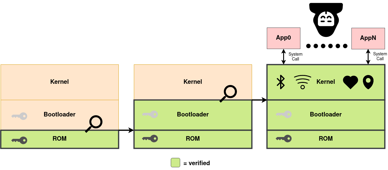
Read it left to right. In the first panel only the ROM is green, and everything above it is unverified. In the second the ROM has checked the bootloader, so the bootloader is green too. In the third the bootloader has checked the kernel, and the whole privileged stack is verified. The keys drawn inside the ROM and the bootloader are what each stage checks the next one against, and the thick black lines are another part of the story, which we will get to shortly.
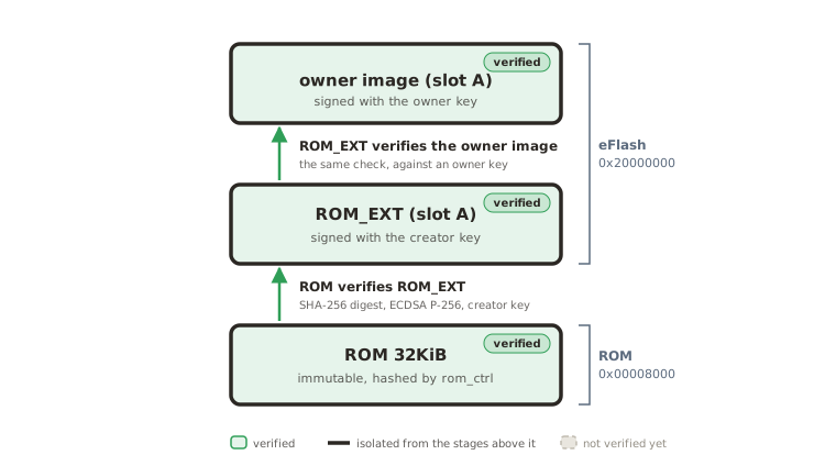
Egret’s chain has the same shape with different names. Its three stages are ROM, ROM_EXT, and the owner image, and the rest of this chapter is that picture redrawn one stage at a time with Egret’s memory map on it.
Verify first, then hand over
Two rules make this so-called “chain of trust” to work:
The first is the obvious one: no stage runs until the stage before it has checked a signature over it. What “checked” means concretely is a hash (e.g., SHA-256) digest for integrity and a signature (e.g., ECDSA P-256) over that digest for authenticity.
The second rule is about what happens after the check passes. Namely, booting should be one-way. Pavona’s logical security model states it in capital letters: from ROM through every software stage, execution is ONE WAY, and each stage completes its task and irreversibly jumps to the next. Once ROM has jumped, nothing later has any legitimate reason to read ROM’s memory, so ROM can lock itself away on the way out and never need it back. This applies to later stages as well. Those thick black lines in the diagram above denote that closing-off, and on Egret this is achieved by something called (e)PMP, which has its own chapter. For now, just note that every arrow in the diagrams below is doing two things at once: verifying, and isolating.
Where the chain is anchored
Every stage in this chapter checks a signature against a key the previous stage handed it. So the chain has to start somewhere, and the first stage has no earlier stage to hand it anything. There is no signature to check ROM against, because there is nothing before ROM to sign it.
Since this is a physical chip, the anchor has to be the hardware itself, and on
Egret that hardware is rom_ctrl. It runs before the CPU executes a single ROM
instruction (see the ROM controller theory of operation for
the details).
On reset, rom_ctrl streams the entire contents of ROM through a cSHAKE256
operation via the KMAC (Keccak message authentication code) hardware
block, then compares the resulting digest against a 256-bit hash stored in the
top eight words of ROM itself. The FSM (finite-state machine) that drives
this reads that expected digest straight from the ROM bus and wires the result
to both the power manager and the key manager:
Pavona hw/ip/rom_ctrl/rtl/rom_ctrl_fsm.sv:282-292
assign exp_digest_o = rom_data_i;
assign exp_digest_vld_o = reading_top;
assign exp_digest_idx_o = rel_addr;

// The 'done' signal for pwrmgr is asserted once we get into the Done state. The 'good' signal
// comes directly from the checker.
assign pwrmgr_data_o = '{done: in_state_done, good: checker_good};

// Pass the digest all-at-once to the keymgr. The loose check means that glitches will add
// spurious edges to the valid signal that can be caught at the other end.
assign keymgr_data_o = '{data: digest_i, valid: mubi4_test_true_loose(in_state_done)};
Two different things happen with that result. The power manager gets a pass/fail
bit it can use to decide whether to let the chip boot at all, and the key manager
gets the raw digest, forwarded unconditionally, whether or not it matched. That
raw digest becomes the first material for something called the CreatorRootKey.
As a result, a ROM that an attacker has modified does not
merely fail to boot, it produces the wrong root key, so every identity and
every key derived from it downstream becomes wrong too. This is the hardware
we root trust in!
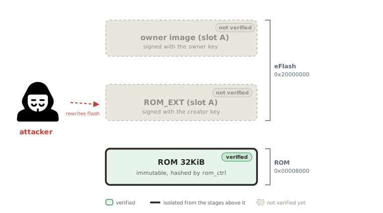
rom_ctrl
has already checked ROM; the two flash stages are still just unverified bytes.
Hop 1: ROM verifies ROM_EXT
From here the same steps repeat for every remaining stage, Pavona’s
secure boot spec explains it in detail. In summary: load the next stage’s
manifest, hash its contents together with a set of usage constraints, and check
the manifest’s signature against that digest and a public key already baked into
the current stage. For ROM, that means computing
SHA256(usage_constraints || rom_ext_contents) and verifying it against a
Silicon Creator public key baked into ROM itself
(see upstream sw/device/silicon_creator/lib/manifest.h:203-235).
Note, Egret keeps two ROM_EXT slots, and ROM always verifies whichever one carries the higher security_version, which makes anti-rollback part of the choice of what to
verify rather than a separate check (sw/device/silicon_creator/rom/boot_policy.c:25-27).
For simplicity this lab only ever populates slot A, so you will not see that fallback.
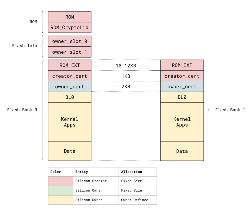
Those slots are real addresses (see hw/top_egret/doc/memory_map.md, or EGRET_SLOTS
in hw/top_egret/defs.bzl). The lab we’ll do later uses opentitantool image assemble to build one simplified image reusing the same slot offsets without the full two-bank
layout.
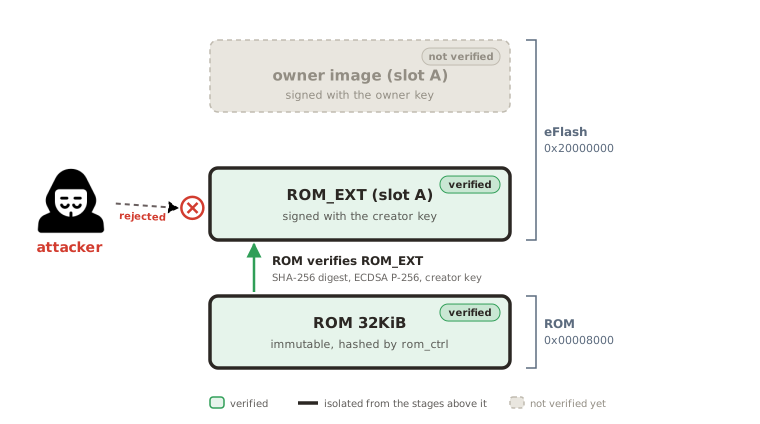
Once the signature is verified, ROM unlocks flash execution over the ROM_EXT region and jumps to it. This covered both rules we mentioned above: the signature decided that ROM_EXT may run, and an ePMP configuration decided what it may reach.
Hop 2: ROM_EXT verifies the owner image
ROM_EXT repeats the same as above with one thing changed: it verifies against a
Silicon Owner public key instead of a Silicon Creator one.
This acts as the handoff from creator-controlled trust to owner-controlled trust, which is the boundary the front matter drew between the two entities, now happening as one concrete key lookup in the middle of a boot. The spec calls this stage’s target BL0, but we’ll call it the owner image going forward.
rom_ext.c’s rom_ext_boot() measures the owner block and derives DICE
attestation keys for it before verifying and jumping
(see sw/device/silicon_creator/rom_ext/rom_ext.c:227-318). We’ll take about DICE derivation later in this book (Part 4).
Note
“The owner” just means whoever’s key ROM_EXT is currently configured to accept. What ownership is and how it changes hands is covered in Part 7. Here it matters only because we’ll soon start working with a blank device, which, on first boot, has no owner configured yet. The
sku_creator_owner_initmethod (sw/device/silicon_creator/lib/ownership/test_owner.c:98) writes a default owner page carrying theAPP_PROD_ECDSA_P256key and continues the boot process. So we’ll see the owner image signed withapp_prod_ecdsa, it’s the key ROM_EXT just gave itself permission to trust.
What happens when verification fails
Everything so far describes the boot chain’s happy path. A secure boot design also has to decide what it does when a check fails. Halting outright is the simplest option, but a bad one for a device in the field…since recovering it then needs physical access and likely a trip back to the manufacturer. Entering some defined failure logic that reports the problem is definitely better…but only if there is anyone around to hear it. A third option is to recover: keep a known-good image in memory the boot code alone can reach, and restore from it when a check fails (see Dave et al.).
Egret’s different stages recover in different ways. A ROM_EXT that fails ROM’s check ends in the ROM’s own shutdown path, which reports an error code and stops outright. Moving up, an owner image that fails ROM_EXT’s check leads into a rescue protocol instead, ROM_EXT’s route to being handed a replacement image rather than simply refusing to continue. We’ll look at both of these cases in reading the boot log.
Watching it happen
A fully successful boot prints about thirty lines, reading the boot log goes through all of them, but here’s a snippet:
 OpenTitan:4001-0002-01
ROM_EXT:0.110
verify: key=2;P256;prod
entry: 0x20010480
The first two lines are ROM and ROM_EXT announcing themselves, which means hop one is
already finished by the time the second line prints. verify: key=2;P256;prod
is ROM_EXT naming the exact key slot, algorithm and role it is about to check
the owner image against, which shows us hop two happening at this one line of output.
entry: 0x20010480 is the jump address, and everything the chip prints after it is
running with control handed all the way up to code an owner signed.
Next, signing and verifying an image opens up the step this chapter drew as an arrow: what the signature actually covers, which key gets picked out of which set, and,briefly, the coprocessor that does the arithmetic.
Signing and verifying an image
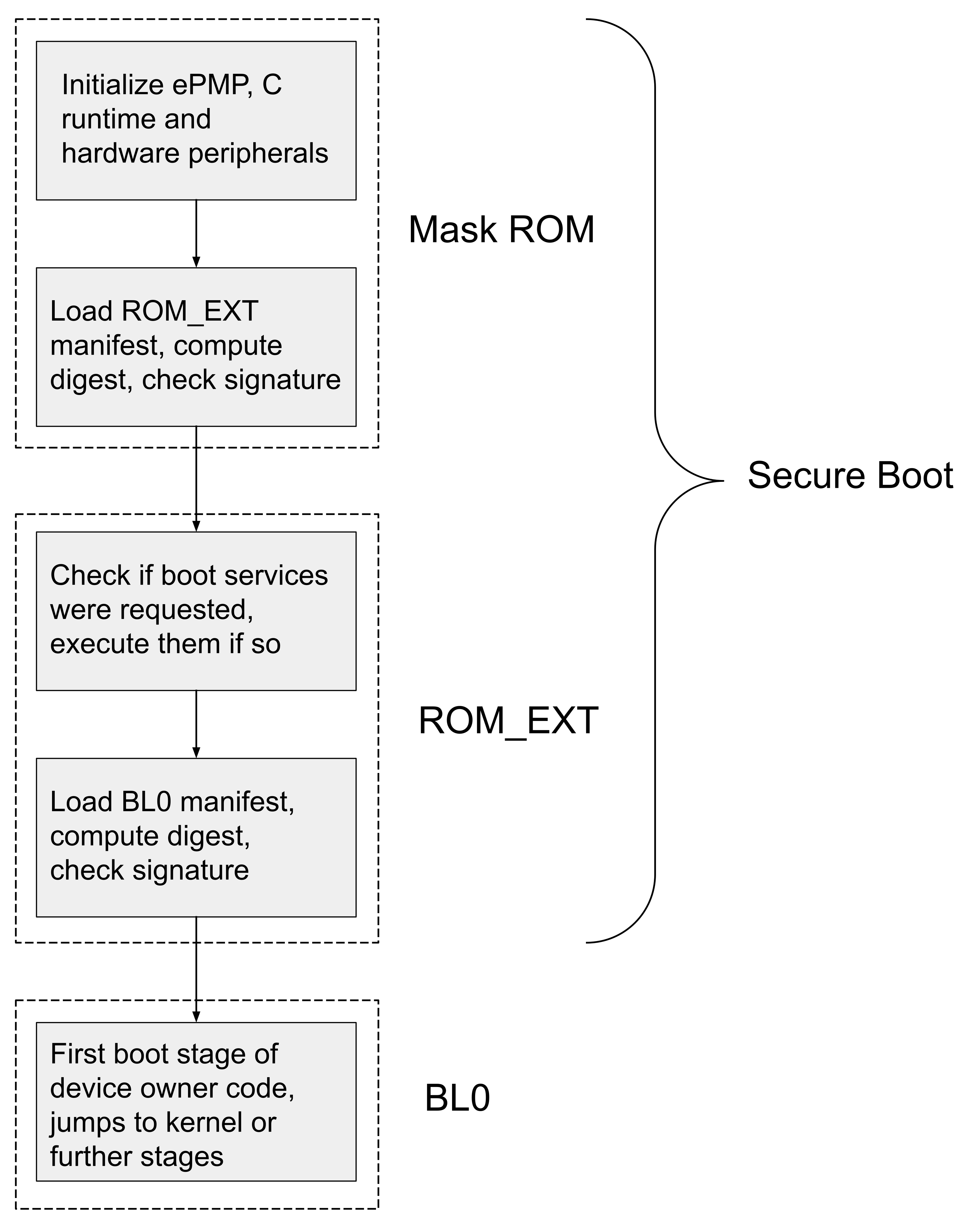
The previous chapter drew each hop of the boot chain as a green arrow: one stage verified the next before handing over control to the next. Each of these arrows adhere to are the same mechanism, and three questions can help guide us through it:
- What does the signature actually cover?
- Which key gets checked against?
- What hardware, if any, does the calculations?
What the signature covers
Every image starts with a 1024-byte manifest, and the digest covers everything from that header onward: the public key, the version fields, and all of the code (the signature itself is excluded, since nothing can sign over itself).
One field is not taken from the image at all. Instead of hashing the manifest’s own copy of the so-called “usage constraints” (see box below), ROM reads those values off the chip itself and hashes what the hardware says.
Note
Usage constraints hold device properties, each of which the signer can either pin to a value or leave open:
device_id, the per-chip identifier in OTP, selectable one word at a timemanuf_state_creatorandmanuf_state_owner, the creator and owner manufacturing states, also from OTPlife_cycle_state, what the lifecycle controller currently reportsA
selector_bitsword says which of the four are pinned. At verification time, ROM fills the pinned ones in from hardware and replaces the rest with a fixed placeholder, then hashes the result. The manifest documentation describes each field and its selector bit, and the sigverify documentation has the final substitution as a one-line formula.
Notably, binding is enforced by the hash, so there is no branching if-else style check anywhere in the code and nothing for an attacker to glitch past. This means that if you tried to run the image from somewhere it does not belong, the digest will simply come out different and the signature will fail.
Anti-rollback works the same way. An image whose security_version is below the
chip’s minimum is not rejected outright. ROM poisons the hash input with
0xFFFFFFFF so that the signature cannot verify, putting failure in the
arithmetic itself rather than in a branch statement.
Which key
The manifest names its signing key and the verifying stage looks for a match.
ROM searches Silicon Creator keys fixed at manufacturing time, each restricted by role to particular lifecycle states (the secure boot spec section has the table).
ROM_EXT searches a keyring of Silicon Owner keys read from the owner page, which
is why that page has to exist before ROM_EXT can verify anything, and why the
lab we’ll do later signs its owner image with app_prod_ecdsa.
Who does the calculations
Egret verifies using the acc block, an asymmetric-cryptography coprocessor, rather than on the main core. ROM hands it the public key, the digest, and the signature, then
reads back a recovered value. There is support for some post-quantum configuration in acc, which we’ll explore later in Part 6.
This last step is another place we can notice the avoidance of if-else style conditional logic (to avoid glitch attacks). If we look at the code, we see that rather than compare the recovered value against the signature, the code XORs it against constants fixed at build time, so a correct signature produces exactly the value that unlocks flash execution and anything else produces garbage and an error. As a result, the permission to run gets derived from the signature being right, instead of by a branch that a fault could skip.
Note
How the XOR check works. The unlock value is never stored. The binary holds eight constants (
kSigverifyShares) chosen so that XOR-ing them together produces it, and only a correct signature makes the recovered value collapse to those shares. Try it: XOR the eight constants insw/device/silicon_creator/lib/sigverify/ecdsa_p256_verify.cand you get0x2f06b4e0, thekSigverifyEcdsaSuccessdefined alongside it. The comments in that file actually walk you through the derivation too, so check it out!
RTFM
Everything above is mostly covered by five files in the Pavona tree, if you want to follow and learn more, check them out:
- Manifest layout and the hashed region:
sw/device/silicon_creator/lib/manifest.h - Usage constraints read from hardware:
sw/device/silicon_creator/lib/sigverify/usage_constraints.c - Hash ordering and the anti-rollback poisoning word:
rom_verifyinsw/device/silicon_creator/rom/rom.c - Key selection and the XOR check:
sw/device/silicon_creator/lib/sigverify/ecdsa_p256_verify.c - The handoff to the coprocessor:
sw/device/silicon_creator/lib/acc_boot_services.c
The lab we’ll do next is where we get to build a real signed image, assemble it into flash, and watch both hops run (simulated) on our own machine.
Building and running a signed chain
Enough theory, let’s get the last two chapters running on our own machine! In this chapter, we’re going to write an silicon-owner program, have Bazel sign it with an owner key, assemble it into a flash image alongside a signed ROM_EXT, and boot it all using Verilator through the real secure boot ROM.
Every command below runs from the root of the upstream Pavona repo, inside the toolchain container we covered in part 1.
This will be a two-hop boot process, but will have one flash image in the end that is itself comprised out two separately signed images (placed at two different memory offsets). We’ll start start by creating our very own owner image, then build it, create a final flash image with a ROM_EXT build from already provided code plus our owner image, and, finally, boot it in Verilator.
The owner image
Create a directory lab/ at the top of your Pavona checkout, and put two files
in it. Both files can be downloaded directly here if you prefer: owner_hello.c and BUILD.
First lab/owner_hello.c, which is the program that gets to run only if both
signature checks pass. It uses the OTTF, the on-target test framework Part 1’s
hello_world also ran under:
// The second hop of the boot chain. ROM verifies ROM_EXT, ROM_EXT verifies
// this, and reaching test_main shows that both signatures checked out.
#include "sw/device/lib/runtime/log.h"
#include "sw/device/lib/testing/test_framework/ottf_main.h"

OTTF_DEFINE_TEST_CONFIG(.enable_concurrency = false,
                        .console.test_may_clobber = false, );
bool test_main(void) {
  LOG_INFO("owner_hello: the owner image is running");
  return true;
}
Returning true from test_main is what eventually prints PASS! - which will, in this case, also proves that ROM has verified ROM_EXT, and ROM_EXT has verified this image.
Next, lab/BUILD, which is shown and described below piece-by-piece.
We start with loads, which pull in the manifest rule and Pavona’s own binary rule:
load("//rules:const.bzl", "CONST", "hex")
load("//rules:manifest.bzl", "manifest")
load("//rules/pavona:defs.bzl", "pavona_binary")
Next, the manifest. This is the 1024-byte header
the previous chapter briefly discussed; this is us now declaring one ourselves.
CONST.OWNER is 0x3042544f (rules/const.bzl:18), the same
value as CHIP_BL0_IDENTIFIER, ROM_EXT will refuse the slot completely if the
identifier does not match (rom_ext_boot_policy.c:66):
manifest({
    "name": "owner_manifest",
    "identifier": hex(CONST.OWNER),
})
Finally the binary itself:
pavona_binary(
    name = "owner_hello",
    testonly = True,
    srcs = ["owner_hello.c"],
    ecdsa_key = {
        "//sw/device/silicon_creator/lib/ownership/keys/fake:app_prod_ecdsa": "prod_key_0",
    },
    exec_env = ["//hw/top_egret:sim_verilator_rom_with_fake_keys"],
    linker_script = "//sw/device/lib/testing/test_framework:ottf_ld_silicon_owner_slot_a",
    manifest = ":owner_manifest",
    # Without this the artifacts are named owner_hello_{name}.*, literal braces
    # included: sim_verilator_rom_with_fake_keys never sets its own exec_env
    # string, and the default "{name}" is used unformatted.
    naming_convention = "{name}",
    deps = [
        "//sw/device/lib/runtime:log",
        "//sw/device/lib/testing/test_framework:ottf_main",
    ],
)
There are 3 attributes we need to focus on.
ecdsa_keynamesapp_prod_ecdsaas the signing key, which is the one the previous chapter explained ROM_EXT will have just written into its own owner page on first boot.exec_envselectssim_verilator_rom_with_fake_keys, the environment that boots the real secure boot ROM instead of the test ROM.linker_scriptplaces the image at the owner slot A offset, so the address it is linked for matches the address you are about to assemble it to.
Build
Let’s build it! Run the following from the base of the Pavona repo:
./bazelisk.sh build --jobs=4 \
  //sw/device/silicon_creator/rom:mask_rom_sim_verilator \
  //sw/device/silicon_creator/rom_ext:rom_ext_dice_x509_slot_a \
  //sw/device/silicon_creator/rom_ext/e2e:otp_img_secret2_locked_rma \
  //hw:verilator //lab:owner_hello //sw/host/opentitantool
The above builds the ROM, a signed ROM_EXT, an OTP image, the Verilator model of the chip, your owner image, and the host tool (phew, that’s a lot!).
Note
The OTP image has to be
otp_img_secret2_locked_rma, not theimg_rmadefault that Part 1 used.img_rmaleaves the SECRET2 partition unlocked, socreator_root_key_validstays low,keymgr_ctrl.svstays inStCtrlInvalid, and ROM_EXT’s immutable section trips aHARDENED_CHECK_EQinimm_section.c. If you chooseimg_rma, things will just fall over silently and it’s very confusing (spoken from experience). If none of the above made sense, no worries, we’ll look more closely at OTP partitions in later parts.
Find the artifacts
The build we just did puts the final device images under a
configuration transition directory (bazel-out/k8-fastbuild-ST-<hash>/bin), while
the OTP image, the Verilator model, and opentitantool all land in the default one.
A nightmare to find and stitch all of this together yourself. Luckily, we can just ask Bazel.
Execute the following set of commands to find all the various artifacts we need. We’ll set each to its own variable so we can reference them later.
BIN=$(./bazelisk.sh info bazel-bin)
EXEC=$(./bazelisk.sh info execution_root)
DEV=$EXEC/$(./bazelisk.sh cquery --output=files //lab:owner_hello 2>/dev/null \
  | grep '/owner_hello\.64\.vmem$' | xargs dirname); DEV=${DEV%/lab}

ROM=$DEV/sw/device/silicon_creator/rom/mask_rom_sim_verilator.39.scr.vmem
ROM_EXT=$DEV/sw/device/silicon_creator/rom_ext/rom_ext_dice_x509_slot_a_sim_verilator.prod_key_0.prod_key_0.signed.bin
OWNER=$DEV/lab/owner_hello.prod_key_0.signed.bin
OTP=$BIN/sw/device/silicon_creator/rom_ext/e2e/otp_img_secret2_locked_rma.24.vmem
VSIM=$BIN/hw/build.verilator_real/lowrisc_dv_top_egret_chip_verilator_sim_0.1/sim-verilator/Vchip_sim_tb
OTT=$BIN/sw/host/opentitantool/opentitantool
Before going any further, check everything got located and set properly:
for v in DEV ROM ROM_EXT OWNER OTP VSIM OTT; do
  printf '%-8s %-7s %s\n' "$v" "$([ -e "${!v}" ] && echo OK || echo MISSING)" "${!v}"
done
Tip
Signed binaries are not default outputs, which is why
ROM,ROM_EXT, andOWNERare built by appending a known filename to a directory Bazel does report. The above loop ensures that any filename that may have drifted from upstream shows up here asMISSINGrather than as a confusing failure later.
Assemble one flash image
"$OTT" --rcfile= image assemble --mirror=false --size=0x80000 \
  --output=twohop.img "$ROM_EXT@0x0" "$OWNER@0x10000"
The two @ offsets are rom_ext_slot_a and owner_slot_a from EGRET_SLOTS
in hw/top_egret/defs.bzl, the same slots
the boot chain chapter showed in the flash layout diagram.
--size=0x80000 matches the flash0 region that --verilator-flash needs.
Now convert to the 64-bit-word vmem the simulator will actually load:
srec_cat twohop.img --binary --offset 0x0 --byte-swap 8 \
  --fill 0xff -within twohop.img -binary -range-pad 8 \
  --output twohop.64.vmem --vmem 64
Note
The commands above may seem random/crazy, but they are actually from Pavona’s own
convert_to_vmemrule (rules/pavona/transform.bzl). There is also a Bazel rule that does the assemble and the conversion in one target,pavona_binary_assembleinrules/pavona/cc.bzl, but those are only usable from the FPGA and silicon environments. Doing it by hand is more fun anyways.
Run it
Run this from a dedicated directory:
"$OTT" --rcfile= --logging=info --interface=verilator \
  --verilator-bin=$VSIM --verilator-rom=$ROM --verilator-otp=$OTP \
  --verilator-flash=twohop.64.vmem \
  console --non-interactive --timeout=3600s --logfile=console.log \
  --exit-success='PASS.*\n' --exit-failure='(FAIL|FAULT).*\n'
The simulator will write uart0.log and trace_core_00000000.log into its working directory.
The console will show a handful of warnings and one error: line about
certificates and ownership. They are expected on a device that has never been
provisioned, and the boot continues through them.
See reading the boot log for more details.
Watch it run
You may notice long silent stretches after some initial output on the UART, and it may be are hard to tell the silence apart from a hang.
So, open a second shell in the run directory and start watching. The Verilator model includes Ibex’s tracer
(hw/top_egret/chip_egret_verilator.core), enabled unless you pass
+ibex_tracer_enable=0, and it writes one tab-separated line per retired
instruction: time, cycle, PC, encoding, decoded instruction, and the registers
or memory touched (hw/vendor/lowrisc_ibex/rtl/ibex_tracer.sv).
Run the following command to get a live feed of execution:
tail -f trace_core_00000000.log
The output is exactly what we mentioned at the end of
the boot chain chapter, ending in entry: 0x20010480 and then your own program printing "owner_hello: the owner image is running".
Keep twohop.img, twohop.64.vmem, and console.log. The next two chapters
use all three: ePMP memory protection reads the region dump in the
middle of that console log, and reading the boot log has you
corrupt twohop.img on purpose and run this same command again.
ePMP memory protection
In the last few sections we have learned about the boot chain and even got the whole chain running ourself. However, once the upper stages, such as, ROM_EXT, owner code, and further application code start to run and continue to execute…but what is actually stopping an upper stage from from reading and tampering with code and data (e.g., ROM secrets) from the stages below it? A valid signature says a stage is who it claims to be, but says nothing about what that stage can touch. Enhanced Physical Memory Protection (ePMP) is the hardware that answers this question and the subject of this chapter.
The end state
If you ran the lab in the last section and stared at the boot logs long enough, you would notice that it contains lines (coming from ROM_EXT) that print the entire ePMP
configuration immediately before jumping to the owner image
(see dbg_print_epmp() in sw/device/silicon_creator/lib/dbg_print.c and how it’s called from rom_ext.c):
0: 00000000 ----- ---- sz=00000000
1: 00000000 ----- ---- sz=00000000
2: 20010400 ----- ---- sz=00000000
3: 20012148   TOR -X-R sz=00001d48
4: 00000000 ----- ---- sz=00000000
5: 00000000 ----- ---- sz=00000000
6: 00000000 ----- ---- sz=00000000
7: 00000000 ----- ---- sz=00000000
8: 20002e88 ----- ---- sz=00000000
9: 2000b550   TOR -X-R sz=000086c8
10: 00000000 ----- ---- sz=00000000
11: 1001c000   NA4 ---- sz=00000004
12: 20000000 NAPOT ---R sz=00100000
13: 00010000 NAPOT -XWR sz=00001000
14: 40000000 NAPOT --WR sz=10000000
15: 10000000 NAPOT --WR sz=00020000
mseccfg = 00000006
entry: 0x20010480
The above lines show the sixteen numbered PMP entries, each showing an address, addressing mode, and a
permission string, then at the bottom we see mseccfg (Machine Security Configuration Register).
The epmp_defs.h file has definitions of what the letters mean: each entry’s mode is one of OFF,
TOR (top-of-range: this entry and the previous one together bound a region), NA4,
or NAPOT (naturally aligned power of two, decoding address and size together from one register),
and the permission string is read/write/execute, prefixed with a lock bit (not printed out in the logs).
Let’s take a look at some of the rows:
- Entry 3 is
20012148 TOR -X-R sz=00001d48, execute-and-read but not write. In TOR mode it pairs with entry 2, so the region runs from0x20010400to0x20012148, the0x1d48bytes the row reports. This is the owner image’s text region, granted byrom_ext.cas the last ePMP write before handing off to owner code, which is why the printedentry: 0x20010480log is an address inside here. What this means is that the owner code gets to run, but is denied by hardware to rewrite its own code (or any other memory outside its predefined regions). - Entry 9 is
2000b550 TOR -X-R sz=000086c8(so paired with entry 8 similar as above), covering0x20002e88to0x2000b550. This is ROM_EXT’s own code region (seeimm_section_epmp.c), which is, again, deliberately not writable by ROM_EXT itself or anything else. - Entry 12 is
20000000 NAPOT ---R sz=00100000, which is one megabyte of read-only memory starting at the base of flash. - Entry 15 is
10000000 NAPOT --WR sz=00020000, which is all of main RAM left as read-write. This is the one entry that never changes for the entire boot process, as discussed further below. - Entry 13, is the debug ROM at
00010000, which is currently left with full-XWRfull access. This particular value depends on the device’s lifecycle state (our lab has OTP provisioned in the RMA mode, which is why debug access is wide open here); lifecycle mechanisms will be covered in a later part. mseccfg = 00000006sets bits 1 and 2:MMWP(Machine-Mode Whitelist Policy) andRLB(Rule Locking Bypass).MMWPis a deny-by-default posture for all sixteen entries above: any address these sixteen rules do not explicitly cover is inaccessible, no exceptions (or well, yes exceptions…but only the fault kind IYKWIM).
How it got that way
The table above is the end result of a sequence rather than a configuration executed by a single stage. The chip boots naked and screaming (all memory unprotected), but then every stage that runs hands over less than it had and provides the necessary protection. However, each stage doesn’t do much logging as these changes happen in real-time, so the only record is the Ibex instruction trace the were streamed to a file in the lab:
grep -E 'pmpcfg|pmpaddr|mseccfg' trace_core_00000000.log
Most of what comes back is the boot code re-reading its own configuration, but there are the writes hiding in there - let’s take a look.
Three takeaways
At the bottom of this chapter you’ll find references to the code that was referenced in tandem with reading through the trace logs mentioned above. All-in-all, going through this will reveal that the ePMP register writes fall into eight passes across the two-hop boot sequence. We’ll go over three of the most interesting learning takeaways below.
Nothing is executable until it has been verified
On start-up each stage’s code region has its addressing mode and permissions cleared which,
when MMWP is enabled, means it is completely unreachable. It regions only opens up
once the stage below it has finished checking its signature.
Once verified, then access and execution permissions are granted.
This process is repeated a few times: ROM opens ROM_EXT’s text read-execute right after ROM’s check passes,
and ROM_EXT opens the owner’s text read-execute right before it jumps there.
The stuff we covered in signing and verifying an image
exists exactly so that the system can verify before this one write to ePMP is safe to make.
Nothing is inherited
Do a global search through the Pavona codebase for the comment “Reclaim entries 0 ~ 7 from ROM and ROM_EXT IMM_SECTION”, and you’ll find our next takeaway.
Before ROM_EXT boots the owner image it wipes every region ROM built via a simple loop over entries 0 through 7. ROM’s own text, the flash window ROM started with, all of it is cleared in ePMP (and thus access restricted). This shows how trust flows forward up the chain but capability does not. Each level re-grants from scratch whatever the next level needs, so a stage’s reach is only what the stage below it deliberately handed over, never something left lying around.
Code is never writable
Next, note how every code region the chain grants comes out read-execute, and RAM stays read-write and never executable, so nothing that runs can rewrite itself. That holds for ROM, ROM_EXT, and the owner image alike. The one entry in the final table with both write and execute is the debug ROM, and that’s only because our lab configured provisioning as RMA, as noted above. RAM is also the single region that survives the whole boot untouched, being the thing every stage needs and none of them ever executes from.
And more
For reference, here all eight passes alluded to earlier, in order:
| Pass | Who | What changed |
|---|---|---|
rom_epmp_init | ROM, hand-crafted assembly before the C runtime | Activates seven PMP regions. Does not include any of ROM_EXT’s since it is not verified yet. |
rom_epmp_config_debug_rom | ROM | Debug ROM entry (lifecycle state), overrides the assembly’s hardcoded default when debug is enabled. |
rom_epmp_unlock_rom_ext_rx | ROM | Opens ROM_EXT as read-execute. Only after the signature check has passed. |
imm_section_epmp_reconfigure | ROM_EXT | Reconfigures MMIO access, the stack guard, and flash, opening ROM_EXT’s own immutable text section, and dropping the rest. |
imm_section_epmp_mutable_rx | ROM_EXT | Opens the rest of ROM_EXT’s code, past the immutable section. |
rom_ext_init | ROM_EXT | Clears entries 0 through 7. Everything ROM set is cleared. |
epmp_clear_lock_bits | ROM_EXT | Unlocks every entry so the last pass can rewrite them. |
epmp_set_tor(2, ...) | ROM_EXT | Hands the owner its read-execute region, sized determined by the given manifest, right before the jump. |
No write anywhere in the trace touches an address above 0x20010000, where the
owner image lives. The owner never configures ePMP at all.
It instead just boots inside a locked jail created by the stages before it.
A compromised or malicious owner image, even one that somehow obtained a valid
signature, cannot (over)write its own code, and whatever has not been explicitly granted to access
is denied by MMWP.
Overall, the signature chain decides who gets to run next; ePMP decides what they are physically capable of touching once they do. These two mechanisms work together to improve the security guarantees of the overall system.
RTFM
All of the above can be found in roughly six files from the Pavona repo:
- ROM’s initial setup, in assembly:
sw/device/silicon_creator/rom/rom_epmp_init.S - ROM’s lifecycle fix and the ROM_EXT grant:
sw/device/silicon_creator/rom/rom_epmp.c - ROM_EXT’s reshuffle and its own code regions:
sw/device/silicon_creator/rom_ext/imm_section/imm_section_epmp.c - The reclaim loop and the owner grant:
sw/device/silicon_creator/rom_ext/rom_ext.c - The driver all of them call:
sw/device/silicon_creator/lib/drivers/epmp.c - The in-memory shadow copy and its check:
sw/device/silicon_creator/lib/epmp_state.c
Next up we’ll take a quick look at the serial boot log output and close off this part.
Reading the boot log
Before we close this part off, let’s take a closer look at the logs our lab produced, and then go break things on purpose to see what the chip has to say about it.
The happy path
The happy path is what we saw in the lab chapter. In that chapter we hid some of the logs for brevity, now below here is the full output that you would see if you ran it yourself:
 OpenTitan:4001-0002-01
ROM_EXT:0.110
IMM_SECTION:0.3-00000000
info: imm_section hash unenforced
warning: corrupted FactoryCerts page
warning: corrupted DiceCerts page
error: UDS certificate not valid
warning: CDI_0 certificate not valid; updating
ownership: \x00\x00\x00\x00
sku_creator_owner_init: saved to flash
info: rescue protocol X
verify: key=2;P256;prod
warning: CDI_1 certificate not valid; updating
[... sixteen ePMP region lines and mseccfg, see epmp.md ...]
entry: 0x20010480
I00001 ottf_main.c:175] Running lab/owner_hello.c
I00002 ottf_main.c:182] Enabling OTTF alert catcher
I00003 owner_hello.c:18] owner_hello: the owner image is running
I00004 ottf_main.c:114] Finished lab/owner_hello.c
I00005 status.c:37] PASS!
The first three lines are the stages announcing themselves: ROM, then ROM_EXT, then ROM_EXT’s own immutable section, which runs before the mutable part of ROM_EXT does.
Then come a handful of lines complaining about certificates, which we can more-or-less ignore. The device has never been provisioned, so it has no valid certs to find. Certificates and the DICE identities behind them are covered in a later part.
Next, ownership: \x00\x00\x00\x00 and sku_creator_owner_init: saved to flash
are ROM_EXT saying that no owner has been configured (hence the four NUL bytes).
ROM_EXT writes itself a default owner and keeps going, which is why we had to
sign with app_prod_ecdsa for this lab (it is the key that default owner expects).
Ownership as a concept, and how it changes over time, is covered in a later part too.
The next info: rescue protocol X line is not the chip entering rescue. It comes from
rescue_detect_entry (sw/device/silicon_creator/lib/rescue/rescue.c),
which runs on every single boot to decide whether a rescue was actually
requested/needed, and prints which protocol this build speaks (X for XMODEM).
Our lab example didn’t cause any trigger of this, so the boot process carries on normally.
Finally the two lines that belong to the boot chain itself.
verify: key=2;P256;prod is the key selection
the signature chapter examined, and
entry: 0x20010480 is the jump into the owner image.
Everything below it is our own owner program running.
Great, now let’s break things!
Making it fail
Recall that the lab’s flash image passes through two steps before Verilator ever sees it:
opentitantool image assemble stitches the signed ROM_EXT and the signed owner
image into our twohop.img, and srec_cat converts that to the final .vmem the
simulator loads. If we want to emulate an attacker, we can do things to
twohop.img and pretend that this is what an attacker with write access could do to flash on an actual running system.
So, let’s make a single bit flip somewhere that the digest covers and see what happens. Each of the two images is a target, at one of these two offsets:
OFF=2048     # the ROM_EXT image (slot A), mapped at twohop.img@0x0
OFF=69632    # or the owner image, at 0x10000 + 2048
The offsets are chosen so the flip lands somewhere that is properly realized;
each image starts with a 1024-byte manifest (CHIP_MANIFEST_SIZE in
sw/device/silicon_creator/lib/base/chip.h), so byte 2048 is well past the
manifest and its signature field, sitting in the code region the digest actually covers.
The second offset adds that same 2048 offset to 0x10000, which takes us to the owner slot the lab assembled.
The sections below will take you through both cases, by first doing a new image assemble, flipping a bit, doingsrec_cat again, then running the simulation for each respectively.
Breaking hop one
Neither of the runs below reads the instruction trace the way
the ePMP chapter did, so we can pass +ibex_tracer_enable=0 and
save the simulator writing a line per retired instruction.
--verilator-args hands anything after it straight to the model
(sw/host/ot_transports/verilator/src/subprocess.rs), which is how the plusarg
gets there.
Corrupt the ROM_EXT using the following:
# Assemble the image again
"$OTT" --rcfile= image assemble --mirror=false --size=0x80000 \
    --output=twohop.img "$ROM_EXT@0x0" "$OWNER@0x10000"
# Corrupt it
OFF=2048
python3 -c "import mmap; f=open('twohop.img','r+b'); m=mmap.mmap(f.fileno(),0); m[$OFF]^=1"
# Generate the simulator vmem image
srec_cat twohop.img --binary --offset 0x0 --byte-swap 8 \
    --fill 0xff -within twohop.img -binary -range-pad 8 \
    --output bad-romext.64.vmem --vmem 64
# Run the simulation
"$OTT" --rcfile= --logging=info --interface=verilator --verilator-bin=$VSIM --verilator-rom=$ROM --verilator-otp=$OTP --verilator-flash=bad-romext.64.vmem --verilator-args=+ibex_tracer_enable=0 console --non-interactive --timeout=900s --logfile=bad-romext.console.log --exit-success='PASS.*\n' --exit-failure='BFV.*\n'
The result looks like:
 OpenTitan:4001-0002-01
BFV:07535603
Note
In the above command,
+ibex_tracer_enable=0is set to disable instruction trace logs. This is just to help speed things up since we’re only looking at the console logs. If you want to examine the actual instructions executed, just remove the--verilator-args.
Bingo! There is no ROM_EXT:0.110 line at all, meaning ROM rejected the
corrupted ROM_EXT before ever handing it control.
What about BFV:07535603? Every silicon_creator error is a single 32-bit word
built by the ERROR_ macro as (error_id << 24) | (module << 8) | status.
The module names and per-module error IDs live in sw/device/silicon_creator/lib/error.h,
the status codes in sw/device/lib/base/internal/absl_status.h.
So split the word into 07, 5356, 03 and look each part up: 0x5356 is
ASCII SV for kModuleSigverify, sigverify error 7 is
kErrorSigverifyBadEcdsaSignature, and status 3 is kInvalidArgument.
The P-256 signature did not match as expected, which is exactly what a flipped bit should result in!
Note
The print itself comes from the ROM’s
shutdown_report_error(sw/device/silicon_creator/lib/shutdown.c), which always emits aBFV(boot fault value), then anLCV(the raw lifecycle state), then aVER(the chip’s SCM revision), in that order. Note that we passed--exit-failure='BFV.*\n', so that ends the console the instant the first line matches.
Breaking hop two
Now the other corruption, with ROM_EXT left untouched (note the fresh
image assemble, which recreates the ROM_EXT we just broke above):
# Assemble the image again
"$OTT" --rcfile= image assemble --mirror=false --size=0x80000 \
    --output=twohop.img "$ROM_EXT@0x0" "$OWNER@0x10000"
# Corrupt it
OFF=69632
python3 -c "import mmap; f=open('twohop.img','r+b'); m=mmap.mmap(f.fileno(),0); m[$OFF]^=1"
# Generate the simulator vmem image
srec_cat twohop.img --binary --offset 0x0 --byte-swap 8 \
    --fill 0xff -within twohop.img -binary -range-pad 8 \
    --output bad-owner.64.vmem --vmem 64
# Run the simulation
"$OTT" --rcfile= --logging=info --interface=verilator --verilator-bin=$VSIM --verilator-rom=$ROM --verilator-otp=$OTP --verilator-flash=bad-owner.64.vmem --verilator-args=+ibex_tracer_enable=0 console --non-interactive --timeout=1800s --logfile=bad-owner.console.log --exit-success='PASS.*\n' --exit-failure='BFV.*\n'
This time we get a lot more output:
 OpenTitan:4001-0002-01
ROM_EXT:0.110
IMM_SECTION:0.3-00000000
info: imm_section hash unenforced
warning: corrupted FactoryCerts page
warning: corrupted DiceCerts page
error: UDS certificate not valid
warning: CDI_0 certificate not valid; updating
ownership: \x00\x00\x00\x00
sku_creator_owner_init: saved to flash
info: rescue protocol X
verify: key=2;P256;prod
BFV:07535603
Everything up to verify: key=2;P256;prod matches the happy path line for line.
ROM accepted this run’s ROM_EXT, and ROM_EXT ran its whole startup, default
owner and all. Only then do things diverge: we see BFV:07535603 instead of the
normally happy ePMP info followed by the entry: line.
This time, the corruption is caught at the owner image’s signature check
specifically, not somewhere in ROM_EXT’s startup and not by the ROM. Neat!
The code decodes to the same kErrorSigverifyBadEcdsaSignature, as expected.
This time though, what print the error log lin was ROM_EXT’s own dbg_printf()
(see sw/device/silicon_creator/rom_ext/rom_ext.c), not the ROM.
This is exact split the boot chain chapter covered: ROM completes execution, hands over to ROM_EXT, then ROM_EXT verifies and catches the bad owner image (but if you look closer, you’ll find it at least offers a way to be given a new valid replacement image later via rescue).
RTFM
Most of the above findings were gleaned from four main files in the upstream Pavona tree:
- The error encoding, the module list, and the numbered constants:
sw/device/silicon_creator/lib/error.h - The general status codes comes from:
sw/device/lib/base/internal/absl_status.h - ROM’s shutdown path and the
BFV/LCV/VERsequence:sw/device/silicon_creator/lib/shutdown.c - ROM_EXT’s own failure print and its support for rescue:
sw/device/silicon_creator/rom_ext/rom_ext.c
That wraps up Part 2. Egret verified a real signed boot chain across two hops, isolated each stage off with ePMP along the way, and refused two different tampered images (which we could trace back to specific lines of source code because Pavona is open source <3). Next we’ll look at how secrets can be stored in Pavona and how different secrets relate to different points in the device’s lifecycle.
References
Abera, Tigist, Asokan, N., Davi, Lucas, Koushanfar, Farinaz, Paverd, Andrew, Sadeghi, Ahmad-Reza, and Tsudik, Gene (2016). “Invited - Things, Trouble, Trust: On Building Trust in IoT Systems”. Proceedings of the 53rd Annual Design Automation Conference (DAC ’16), ACM.
Aerabi, Ehsan, Bohlouli, Milad, Ahmadi Livany, Mohammad Hasan, Fazeli, Mahdi, Papadimitriou, Athanasios, and Hély, David (2020). “Design Space Exploration for Ultra-Low-Energy and Secure IoT MCUs”. ACM Transactions on Embedded Computing Systems, vol. 19, no. 3. pp. 19:1-19:34.
Asokan, N., Nyman, Thomas, Rattanavipanon, Norrathep, Sadeghi, Ahmad-Reza, and Tsudik, Gene (2018). “ASSURED: Architecture for Secure Software Update of Realistic Embedded Devices”. IEEE Transactions on Computer-Aided Design of Integrated Circuits and Systems, vol. 37, no. 11. pp. 2290-2300.
Aumasson, Jean-Philippe (2017). “Serious Cryptography: A Practical Introduction to Modern Encryption”. No Starch Press.
Bar-El, H., Choukri, H., Naccache, D., Tunstall, M., and Whelan, C. (2006). “The Sorcerer’s Apprentice Guide to Fault Attacks”. Proceedings of the IEEE, vol. 94, no. 2. pp. 370-382.
Brasser, Ferdinand, El Mahjoub, Brahim, Sadeghi, Ahmad-Reza, Wachsmann, Christian, and Koeberl, Patrick (2015). “TyTAN: tiny trust anchor for tiny devices”. Proceedings of the 52nd Annual Design Automation Conference, ACM. pp. 34:1-34:6.
Bricker, George (2013). “Unified Extensible Firmware Interface (UEFI) and Secure Boot: Promise and Pitfalls”. Journal of Computing Sciences in Colleges, vol. 29, no. 1. pp. 60-63.
Burg, Andreas, Chattopadhyay, Anupam, and Lam, Kwok-Yan (2018). “Wireless Communication and Security Issues for Cyber-Physical Systems and the Internet-of-Things”. Proceedings of the IEEE, vol. 106, no. 1. pp. 38-60.
Dave, Avani, Banerjee, Nilanjan, and Patel, Chintan (2021). “CARE: Lightweight Attack Resilient Secure Boot Architecture with Onboard Recovery for RISC-V based SOC”. CoRR.
Diehl, W., Farahmand, F., Yalla, P., Kaps, J., and Gaj, K. (2017). “Comparison of hardware and software implementations of selected lightweight block ciphers”. 27th International Conference on Field Programmable Logic and Applications (FPL). pp. 1-4.
Francillon, Aurélien and Castelluccia, Claude (2008). “Code injection attacks on harvard-architecture devices”. ACM Conference on Computer and Communications Security (CCS), ACM. pp. 15-26.
Frazelle, Jessie (2020). “Securing the Boot Process: The Hardware Root of Trust”. Queue, vol. 17, no. 6. pp. 5-21.
Goodspeed, Travis (2008). “Stack Overflow Exploits for Wireless Sensor Networks Over 802.15.4”.
Google Security Blog. “OpenTitan - open sourcing transparent, trustworthy, and secure silicon”.
Hahm, O., Baccelli, E., Petersen, H., and Tsiftes, N. (2016). “Operating Systems for Low-End Devices in the Internet of Things: A Survey”. IEEE Internet of Things Journal, vol. 3, no. 5. pp. 720-734.
Haj-Yahya, Jawad, Wong, Ming Ming, Pudi, Vikramkumar, Bhasin, Shivam, and Chattopadhyay, Anupam (2019). “Lightweight Secure-Boot Architecture for RISC-V System-on-Chip”. 20th International Symposium on Quality Electronic Design (ISQED), IEEE. pp. 216-223.
Huang, Andrew (2020). “Evaluating Precursor’s Hardware Security”.
Johnson, Scott (2018). “Titan: enabling a transparent silicon root of trust for Cloud”. Hot Chips 30.
Kelly, Bryan (2018). “Project Cerberus Security Architecture Overview Specification”.
Khanam, Shapla, Ahmedy, Ismail Bin, Idris, Mohd Yamani Idna Bin, Jaward, Mohamed Hisham, and Sabri, Aznul Qalid Md (2020). “A Survey of Security Challenges, Attacks Taxonomy and Advanced Countermeasures in the Internet of Things”. IEEE Access, vol. 8. pp. 219709-219743.
Koeberl, Patrick, Schulz, Steffen, Sadeghi, Ahmad-Reza, and Varadharajan, Vijay (2014). “TrustLite: a security architecture for tiny embedded devices”. Ninth Eurosys Conference, ACM. pp. 10:1-10:14.
Levy, Amit, Campbell, Bradford, Ghena, Branden, Giffin, Daniel B., Pannuto, Pat, Dutta, Prabal, and Levis, Philip (2017). “Multiprogramming a 64kB Computer Safely and Efficiently”. Proceedings of the 26th Symposium on Operating Systems Principles (SOSP ’17), ACM. pp. 234-251. (the Tock OS paper)
Maene, Pieter, Götzfried, Johannes, de Clercq, Ruan, Müller, Tilo, Freiling, Felix C., and Verbauwhede, Ingrid (2018). “Hardware-Based Trusted Computing Architectures for Isolation and Attestation”. IEEE Transactions on Computers, vol. 67, no. 3. pp. 361-374.
Microsoft. “Secure boot”.
Obermaisser, Roman, Peti, Philipp, and Tagliabo, Fulvio (2007). “An integrated architecture for future car generations”. Real-Time Systems, vol. 36, no. 1-2. pp. 101-133.
Ojo, Mike Oluwatayo, Giordano, Stefano, Procissi, Gregorio, and Seitanidis, Ilias Nektarios (2018). “A Review of Low-End, Middle-End, and High-End IoT Devices”. IEEE Access, vol. 6. pp. 70528-70554.
Papp, D., Ma, Z., and Buttyan, L. (2015). “Embedded systems security: Threats, vulnerabilities, and attack taxonomy”. 13th Annual Conference on Privacy, Security and Trust (PST). pp. 145-152.
Parno, Bryan, McCune, Jonathan M., and Perrig, Adrian (2010). “Bootstrapping Trust in Commodity Computers”. 31st IEEE Symposium on Security and Privacy, IEEE Computer Society. pp. 414-429.
Profentzas, Christos, Günes, Mirac, Nikolakopoulos, Yiannis, Landsiedel, Olaf, and Almgren, Magnus (2019). “Performance of Secure Boot in Embedded Systems”. 15th International Conference on Distributed Computing in Sensor Systems (DCOSS), IEEE. pp. 198-204.
(2026). “The RISC-V Instruction Set Manual, Volume II: Privileged Architecture”. RISC-V International. Edition 20260120.
Silva, Miguel, Cerdeira, David, Pinto, Sandro, and Gomes, Tiago (2019). “Operating Systems for Internet of Things Low-End Devices: Analysis and Benchmarking”. IEEE Internet of Things Journal, vol. 6, no. 6. pp. 10375-10383.
Trappe, Wade, Howard, Richard E., and Moore, Robert S. (2015). “Low-Energy Security: Limits and Opportunities in the Internet of Things”. IEEE Security & Privacy, vol. 13, no. 1. pp. 14-21.
Tschofenig, Hannes and Baccelli, Emmanuel (2019). “Cyberphysical Security for the Masses: A Survey of the Internet Protocol Suite for Internet of Things Security”. IEEE Security & Privacy, vol. 17, no. 5. pp. 47-57.
UEFI Forum (2020). “Unified Extensible Firmware Interface (UEFI) Specification”. Edition 2.8 B.
van Oorschot, Paul C. (2020). “Computer Security and the Internet: Tools and Jewels”. Springer.
Wolf, Marilyn and Serpanos, Dimitrios N. (2018). “Safety and Security in Cyber-Physical Systems and Internet-of-Things Systems”. Proceedings of the IEEE, vol. 106, no. 1. pp. 9-20.